RK3576 UEFI: Teaching EDK2 to Drive HDMI, USB, and eMMC
TL;DR
- EDK2 boots a real UEFI environment on the RK3576 — swapping out U-Boot proper for EDK2 after BL31, verified on two boards (Radxa ROCK 4D over SPI, ArmSoM CM5-IO over SD).
- HDMI’s worst bug was the debugging itself: reading overlay registers back after enable — read-only, no writes — silently perturbed VOP2 and killed the picture; the one real fix underneath all the phantom bugs was a register-write-ordering issue.
- USB needed two DWC3 xHCI workarounds: skip a structurally-redundant
EvaluateContexton SuperSpeed, and mark the hub slot-context flag before the interrupt endpoint arms, or the onboard hub never enumerates. - eMMC was simply held in hardware reset —
EMMC_RST_Ndefaults to 0, and RK3588 boards never notice because SPL boots from eMMC and clears it in passing; RK3576 booting SD/SPI never touches that bit at all. - Ethernet’s PHY part number was copy-pasted wrong everywhere — four independent sources call it an RTL8211F; the schematic says MotorComm YT8531C. It works either way (both are generic Clause-22 PHYs), until you need PHY-specific tuning.
- Two firmware/OS handoff bugs lived below any single peripheral: a coincidental
MZbyte pair in unrelated memory crashed the OS-loader scan, and an unpopulated RAM bank register read as all-zero decoded into a phantom 256 MB.
Read the full write-up
The goal was a real UEFI firmware on the RK3576: boot the standard chain but swap U-Boot proper for EDK2, so the board comes up to a proper UEFI environment (think ESXi-on-Arm, Windows, EBBR distros). The boot chain:
1 | BootROM → U-Boot SPL (idbloader) → TF-A BL31 → EDK2 UEFI (BL33 @ 0x40800000) |
SPL loads a FIT image — from SPI 0x60000 or SD sector 16384 — containing BL31 and
EDK2. The unbreakable rule: U-Boot proper must never end up in that FIT. Half of
the early bugs were exactly that leaking back in (u-boot.bin in the FIT, raw SPL with no
RKNS header, FIT entries pointing at BL31 load addresses that didn’t match the ELF’s
actual segments). Once the packaging was honest, the fun started: three peripherals,
three completely different failure personalities.
Boards: Radxa ROCK 4D (SPI boot) and ArmSoM CM5-IO (SD boot).
HDMI: where reading a register breaks the picture
VOP2 is Rockchip’s display controller, and the RK3576’s is almost the RK3588’s, which is the worst kind of almost. Same register names, subtly different addresses and semantics, and a vendor TRM that documents the happy path and nothing else. What follows is the whole journey, dead ends included, because the dead ends are the actual content.
Tier 1: the things you just have to get right
These cost time but they’re honest hardware facts — read the TRM carefully, cross-check mainline, move on:
- Pixel clock divider is ÷2, not ÷4. RK3588 uses ÷4; RK3576 halves the VOP2 DCLK
core rate (
VPixclk >> 1). Wrong divider, no usable signal. IF_CTRLpin polarity lives in bits [5:4]; for +H/+V sync you write0x80000033.- HPD routing through GPIO4 PC0–PC3, all function 9 (CEC + HPD + SCL + SDA). PC0 specifically must be fn9 or the IOC won’t route hot-plug detect.
IOC_MISC_CON0CLR bit must stay latched — it’s not write-1-to-clear like you’d assume. Clear it and you freeze the hot-plug detector solid.
A note on references: do not use vendor U-Boot as your VOP2 source. Mainline U-Boot
doesn’t bring up VOP2 at all (the OS DRM driver does), so it’s tempting to reach for the
Rockchip vendor tree, which does init the display. It also has its own divergent register
map — rk3528_setup_overlay, a different BG_MIX_CTRL address — and it burned me twice
(a stray LAYER_SEL = 0xFFFFFFFF pre-init, a wrong mix-control address), each time killing
the signal. The only authoritative reference is mainline Linux rockchip_drm_vop2.c /
rockchip_vop2_reg.c.
Tier 2: mainline does X, and you can’t
PRE_DITHER_DOWN_EN = 1kills the signal — even though mainline sets that exact bit for the same RGB888 path. The difference is ordering: mainline computes the entireDSP_CTRLas one localu32and writes it once at the end ofatomic_enable; myVop2Initpokes the register incrementally with read-modify-write and intermediateCFG_DONEcommits. Flip pre-dither mid-sequence and the VP lands in a stateCFG_DONEcan’t complete from, and the output drops. The cost of leaving it0is visible — faint vertical one-pixel banding and a touch less brightness — but Linux rewritesDSP_CTRLat OS handoff, so it’s a UEFI-only cosmetic. Real fix is a compute-then-write refactor; I haven’t done it yet.
Tier 3: the bug that was my own debugger
This is the one I’ll be telling people about for a while.
I had a black screen with a valid signal and went hunting for the blending bug. Standard
move: dump the overlay registers after enable and read them back. So I added a block of
MmioRead32 + DEBUG prints after VP0’s CFG_DONE — OVL_LAYER_SEL, the legacy
OVL_PORT_SEL at 0x608, the old VP0_BG_MIX at 0x6E0, the esmart block. Adding the
dump took down HDMI. Read-only reads. No writes.
The trap is that on RK3576 the OVL block was reorganized: 0x608 and 0x6E0 are
RK3588-legacy addresses that now point at completely different, live registers, and
touching them — even reading — perturbs the VP. (Or it’s the ~10 ms of UART latency at
1.5 Mbaud landing in a tight window between CFG_DONE and the PHY bring-up; I never fully
proved which.) Either way: my diagnostic was the fault. And because the dump moved the
register values I was reading, it manufactured a fake LAYER_SEL bug — so I spent an
afternoon chasing a layer-select problem that did not exist, caused entirely by the act of
looking at it.
Tier 4: debugging a problem that wasn’t there
Here’s the genuinely embarrassing part, kept in on purpose.
Once I stopped reading registers, the monitor synced and — in the half-second I glanced at
it mid-boot — showed black. Valid timing, valid TMDS, nothing on it. So I built a theory:
RK3576’s overlay routes windows differently from RK3588 — per-window VP_SEL registers
plus a per-VP OVL_LAYER_SEL, instead of the central pair at 0x604/0x608 — so surely EDK2
was programming an overlay the chip ignored, and the window was attached to no video port.
It’s a plausible theory; it matches how the mainline RK3576 path is actually written. I
spent an evening implementing it carefully against rockchip_vop2_reg.c, flashed, and
turned a working picture into a dead signal — three builds in a row.
What finally stopped the bleeding was not more theory. It was dumpimage on the one SD
image that actually drove a picture: pull the gzipped EDK2 firmware volume out of the FIT
and check its build timestamp against mine. The working binary was the original,
unmodified overlay — the build where my rework was reverted. The RK3588-style central
OVL_LAYER_SEL/OVL_PORT_SEL path composites perfectly well on RK3576. My rework left the
window half-routed and dropped sync. And the black frame that started the whole detour?
The boot logo simply hadn’t been painted yet at the instant I looked — once BDS draws the
framebuffer, TianoCore is on the glass:
| Radxa ROCK 4D | ArmSoM CM5-IO |
|---|---|
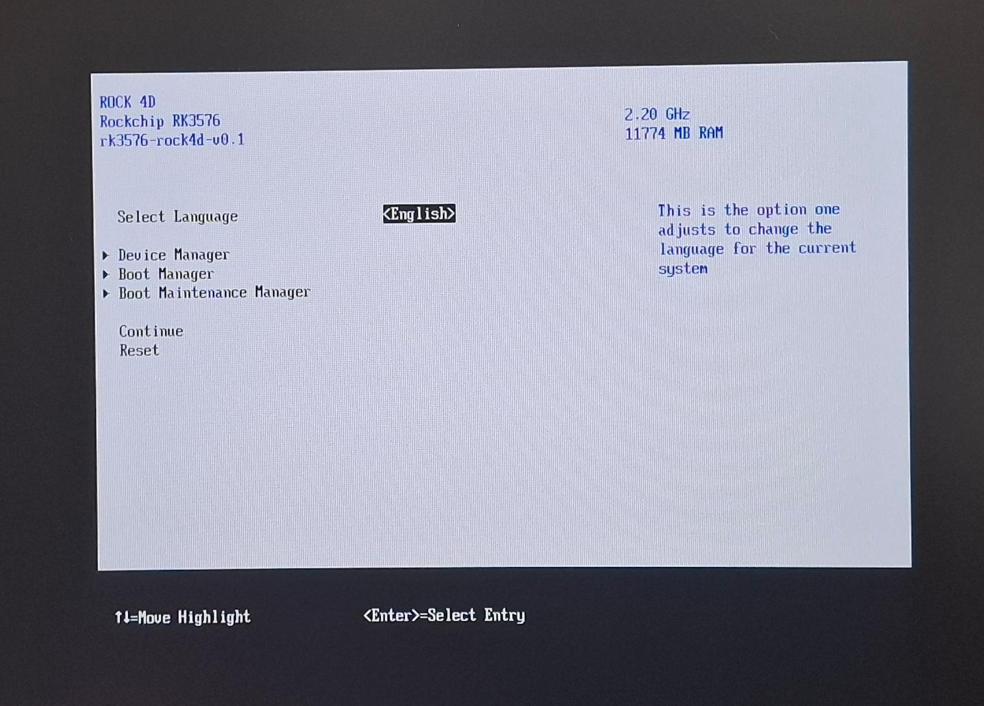 |
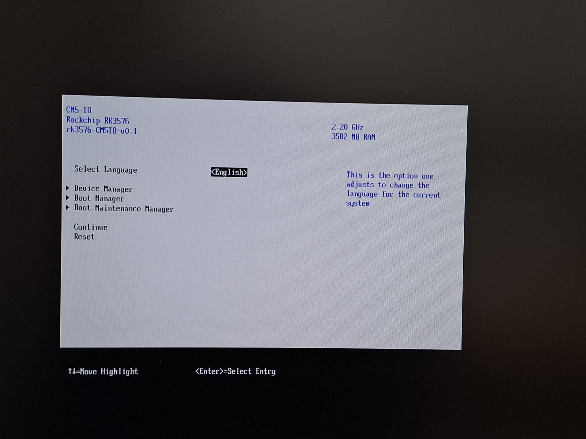 |
So if you skim the edk2-rk3576 git log around the HDMI work it’s a graveyard of fix:
immediately followed by Revert "fix:", and now a revert: of a fix: that fixed
nothing. That isn’t noise — it’s what undocumented display bring-up looks like when your
own tools and your own theories keep generating phantom bugs. Two lessons I actually
internalised:
- On this block, reading is not free. Print computed values before you write them; never read registers back after enable for “just a quick check.”
- Confirm against the working binary before you theorise. Five minutes of
dumpimagewould have saved me an evening of plausible, confident, wrong rework.
The one real bug was the register dump. The only thing left is a small horizontal offset on
CM5-IO — the RK3576 background/pre-scan delay still uses the RK3588 formula, a genuine
one-register fix — and even that was one git revert away the whole time.
USB: a hub that won’t enumerate
CM5-IO routes both USB-A ports through an onboard 4-port USB3 hub IC hanging off DRD1.
No direct port — everything goes through the hub, so if the hub doesn’t enumerate, you
have no USB at all. Two independent DWC3 xHCI bugs, both in EDK2’s XhciDxe:
1. SuperSpeed EvaluateContext times out. The RK3576 DWC3 never raises a Command
Completion event for EvaluateContext on a SuperSpeed slot, so enumeration hangs waiting
for it. The saving grace: on SS, EP0’s max packet size is always 512, which is already
the value the Address-Device context was initialised with. The command is a structural
no-op. So: when MaxPacket0 == 512, skip it and return success. (512 is unique to SS;
HS/FS/LS EP0 is ≤64, so the check can’t misfire.)
2. Hub ConfigHubContext times out after SetConfig. Once the hub’s interrupt
endpoint goes active, the controller serialises Configure-Endpoint commands behind
endpoint-transfer processing and deadlocks. Fix is to set the Hub=1 slot-context flag
before SetConfigCmd activates that endpoint (with a placeholder port count), then
tolerate the later “real values” update failing — the hub’s already marked as a hub, so
it keeps working. (Cost: TT routing for full/low-speed devices behind the hub is
approximate, but HS/SS storage and HID — the stuff people actually plug in — are fine.)
After both: PORTSC shows the SS and HS hub links trained to U0 at ReadyToBoot.
Devices appear. Ship it.
eMMC: held in reset the whole time
SdCardIdentification: Executing Cmd0 fails with Time out. eMMC never showed up. The
root cause is almost funny:
EMMC_EMMC_CTRL bit 2 is EMMC_RST_N, and its power-on default is 0 — eMMC held in
hardware reset. On RK3588 boards this is invisible because SPL boots from eMMC and
clears the reset on its way through. On RK3576 booting from SD or SPI, nothing ever
touches the eMMC controller, so it sits in reset until UEFI tries to talk to a device
that is, electrically, switched off.
Fix: MmioOr32(EMMC_EMMC_CTRL, BIT2) to deassert reset, then a 200 µs stall per the
eMMC spec, before CMD0. Universal — any platform that boots from SD/SPI needs it.
That got CMD0 talking, and then HS200/HS400 hung, which opened a whole second saga of
about seven smaller fixes to get a stable 52 MHz High-Speed mode (ForceHighSpeed): the
SDHCI base-clock value not propagating to the divisor math, the init CRU running at the
wrong frequency, CARD_IS_EMMC only being set on the DLL path, DLL bypass/RXCLK gating
constants lifted from U-Boot’s non-DLL path, an RK3576-specific STRBIN delay (0xa, not
RK3588’s 0x10)… and the one that was the actual CMD0-timeout root cause hiding
under all of it: MISC_INTCLK_EN (the internal-clock enable) gets cleared by
SW_RST_ALL and was never re-set. Mainline’s rk35xx_sdhci_reset() always restores
it after a reset; we weren’t, so the SDHCI internal clock was simply off and every
command timed out. Restoring it after reset is what finally made it stick.
The recurring tell across all of it: the Rockchip SDHCI’s clock divider bits aren’t functional — the real eMMC clock follows the CRU, and the SDHCI divisor is ignored. Once you internalise that, half the “impossible” clock numbers explain themselves.
Ethernet: the part number was a copy-paste
This one barely cost any debugging — it’s here because of how the answer hid. GMAC0 on
the CM5-IO comes up fine; PXE boots, gigabit links. But every text source describing the
PHY agrees it’s a Realtek RTL8211F: the upstream device tree comment says so, the vendor
BSP device tree says so (it even hard-codes a “100 ms for rtl8211f” reset delay), and the
EDK2 port I started from ships a RealtekPhy.c. Four independent files, one part number,
total consensus.
The schematic disagrees. U6601 is a MotorComm YT8531C — a different vendor’s PHY
entirely. Every text source had inherited the same wrong identity by copy-paste, one tree
cribbing from the last, and nobody re-checked against the board. It works anyway because
both are ordinary Clause-22 PHYs and the generic IEEE driver brings either up — so the lie
is invisible as long as you only need a link. It stops being invisible the moment you
want the PHY-specific RGMII skew and delay tuning right, which is the difference between
“links” and “links cleanly at gigabit.” The schematic was the one witness in the room that
hadn’t copied its homework from the others.
The bugs that weren’t peripherals
The two nastiest bugs weren’t in any controller. They lived at the seam where firmware hands off to the OS, and they’re the kind you can only hit on real silicon with real memory contents.
A coincidental “MZ” that crashed the handoff. ExitBootServicesHookDxe identifies the
OS loader by walking backwards from the loader entry looking for an EFI PE image — the
MZ DOS signature (0x5A4D), then e_lfanew to find the PE header. On the ROCK 4D this
was fine. On the CM5-IO it hard-hung before Linux could take over from GRUB. The cause:
some unrelated data page happened to contain the two bytes 4D 5A, the scanner accepted
it as a DOS header, read e_lfanew out of whatever garbage followed, and chased the
“PE header” pointer to 0x184DD0D7C — about 6.2 GB, nowhere near anything mapped. A
translation fault (ESR=0x96000005), and the board was dead one instruction before the
kernel got control. It looked board-specific and random because it was random: it
depended on what bytes were lying around in memory at that address on that board. The fix
is to not trust a bare MZ — a real EFI image keeps its PE header at a small offset, so
reject any e_lfanew outside [sizeof(DOS_HEADER), 1 MB) before following it. Data that
happens to look like code is the oldest trap there is, and it still got me.
256 MB of RAM that didn’t exist. The SDRAM sizing code reads two bank register pairs
out of PMUGRF. The CM5 module is a single 4 GB bank, so the SPL never writes the second
pair — and it reads back as all-zeros. Zero isn’t “no bank,” though; fed through the
bit-field math it decodes to a perfectly plausible 256 MB, so the firmware proudly
reported 4352 MB to SMBIOS. Harmless to the page tables, but a lovely reminder that an
uninitialised register reading 0 is not the same as “absent” — you have to treat
all-zeros as skip this slot, not a 256 MB stick lives here.
The pattern
A handful of peripherals, each with its own lesson, one shape. HDMI: your debugging can
be the bug. USB: the controller’s idea of a no-op isn’t the spec’s. eMMC: the thing
was never powered on, you were talking to a brick. Ethernet: every document agreed, and
the schematic was the only one right. And the two at the seam: data that looks like
code, and zero that looks like a number. None of it came from a register manual — it came
from mainline Linux and U-Boot as the reference for what the working values are, then
flashing real boards and reading what the silicon did. The screen, the PORTSC bits, the
CMD0 timeout, a schematic nobody re-read, and a fault address six gigabytes into nowhere
were the only honest witnesses. Everything else was a theory waiting to be reverted.